Appearance
DTU-Modbus Example
Introduction
DTU (data transmission unit ) is a wireless terminal device specially used to transmit serial data through a wireless communication network. Broadly speaking, during communication, the module units responsible for sending data at both ends of the data transmission link are called DTUs, which perform format conversion, sorting and verification to the transmitted data. This example describes that a hygrothermograph sensor over Modbus Protocol accesses Acceleronix Developer Center through IoT DTU module to communicate with Developer Center.
Related API
| Function | Description |
|---|---|
| Ql_iotMBInit() | Initializes Modbus components. |
| Ql_iotMBCloudRecv() | Converts the format of the TSL data issued by Developer Center to Modbus format and sends the data to Modbus slave. |
| Ql_iotMBLocalRecv() | Forwards Modbus data received via the serial port to Modbus components and processes the Modbus data. |
| Ql_iotMBDeinit() | Deinitializes Modbus components. |
See DTU-Modbus API for details.
Operations on Developer Center
1. Log in to Developer Center
Log in to Developer Center. If you don't have an account, click Register Now to register.
2. Create a Product
Creating a product is the first step in product development. A product is an abstract description of a class of devices defined by Developer Center. A product is used to manage devices of the same category. For example, if you have a hygrothermograph sensor with Wi-Fi networking capability and you need to connect the hygrothermograph sensor to Developer Center to monitor it, you can define it as a product "Smart Hygrothermograph".
Operations on QthTools-DTU_Modbus
QthTools-DTU_Modbus helps you quickly define the features of the slave by using Modbus protocol. After configuring the product information and defining features, you only need to download the configuration file into the DTU module and import it into the Developer Center to connect the slave to Developer Center.
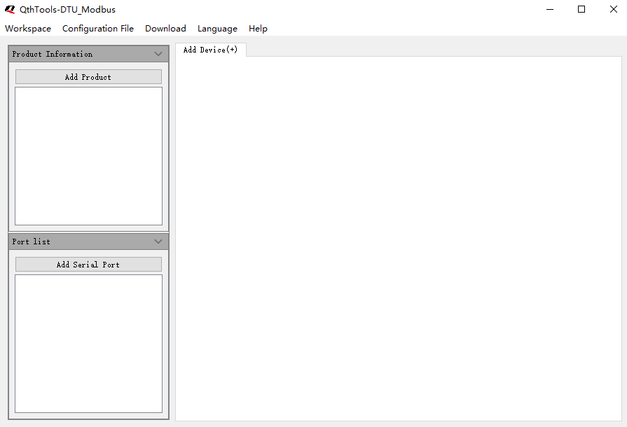
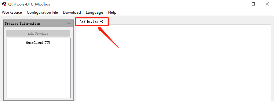
Homepage of the Tool
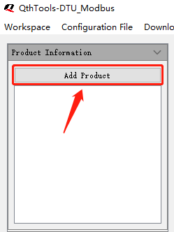
1. Configure Product Information
Click "Add Product" on the left configuration bar.
The pop-up window of "Add Product" is shown below.
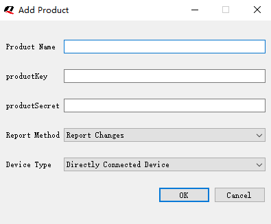
- Product Name: The product name of DTU.
- ProductKey: The ProductKey is generated when a product is created on Developer Center.
- ProductSecret: The ProductSecret is generated when a product is created on Developer Center.
- Report Method: "Report Changes" and "Report All"
- Report All: The data polled each time will be directly reported to Developer Center.
- Report Changes: The data polled each time is compared with the last data, and only changes are reported to Developer Center.
- Device Type: "Directly Connected Device" and "Gateway Sub-device"
- Directly Connected Device: The slave and the gateway share the same product information and are displayed on the Developer Center as a whole device.
- Gateway Sub-device: The slave has independent product information and device information, and is displayed independently on Developer Center.
Note: You can only add one piece of product information at a time. If you need to add a new piece, you must first modify or delete the existing one.
2. Configure Serial Port Information
Click "Add Serial Port" on the left configuration bar.
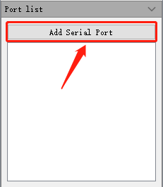
The pop-up window of "Add Serial Port" is shown below.
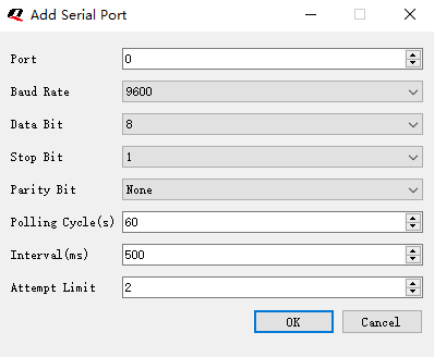
- Port: Port number of the DTU device to connect to the slave.
- Baud Rate: The number of bytes transmitted per second, commonly set to 9600 and 115200. This value needs to be matched with the baud rate of the slave.
- Data Bit: A parameter that measures valid data in communication. Default value: 8. This value needs to be matched with the data bit of the slave.
- Stop Bit: This parameter indicates the transmission end of a character. it can be set to 1, 1.5, or 2. This value needs to be matched with the stop bit of the slave.
- Parity Bit: This parameter can be set to 'None", "Even", "Odd", "Mark" and "Space". Default value: "None". This value needs to be matched with the parity bit of the slave.
- Polling Cycle(s): The time required for the DTU device to send polling of Modbus protocol to the sub-device. For example, the DTU device reads the temperature and humidity values from the sub-device every 60 seconds.
- Interval(ms): To avoid the issue of packet sticking, the minimum interval at which the DTU sends each Modbus protocol to the slave device.
- Attempt Limit: This parameter defines how many times the DTU device will attempt to resend the query data frame of Modbus protocol, if the sub-device (sensor) does not respond within the command interval. If this parameter is set to 0, the DTU device will stop sending data frames.
3. Add Device Information
Note: When selecting "Gateway Sub-device" as the device type, you need to input the corresponding product information for each Modbus device.
1) Click "Add Device(+)" to add a slave.
2) Pop-up window of "Add a Device Model"
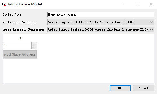
i. Enter the device name of the slave in "Device Name" column, such as "hygrothermograph".
ii. Input the Modbus slave address in the serial port number list. For example, if the hygrothermograph sensor is placed on serial port 1 and the Modbus slave address is 1, you can set the slave address to "1". If multiple devices need to be set to different Modbus slave addresses, add more slave addresses to the list.
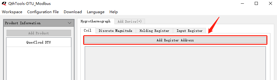
4. Add Feature Register
1) Add Feature Register Address
Select the slave tab and click "Add Register Address ".
Enter the "Start Address" and "Quantity" in the pop-up window.
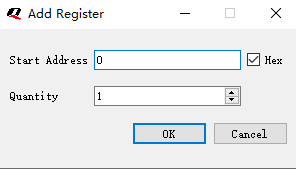
Note: You can display the "Start Address" in either decimal or hexadecimal format by checking the "Hex" option.
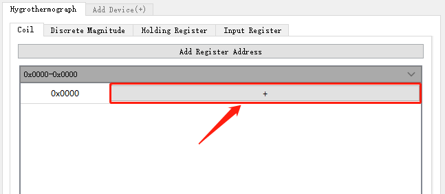
2) Add Register Configuration Information
Click "+" on the right to add register configuration information.
5. Configure Feature Information
You can use QthTools-DTU_Modbus to remotely view and configure the features of a Modbus sensor connected to Developer Center, such as a hygrothermograph. The tool allows you to add feature information to the sensor, including temperature and humidity readings, switch configuration, and real-time clock settings. To demonstrate how to add feature information on QthTools-DTU_Modbus, we will use a hygrothermograph sensor as an example.
The features to be added are listed in the table below.
| Type | Feature Name | Read/Write | Data Type | Byte Order | Formula | Data Length |
|---|---|---|---|---|---|---|
| Boolean | Switch | Read & Write | -- | -- | -- | -- |
| Number | Temperature | Read-only | 16-bit Signed Int | Big Endian | x0.01+0 | -- |
| Number | Humidity | Read-only | 16-bit Unsigned Int | Big Endian | x0.01+0 | -- |
| Byte Stream | Time Stamp | Read & Write | -- | -- | -- | 13 |
| Enumeration | Working Mode | Read & Write | 16-bit Unsigned Int | Big Endian | -- | -- |
1) Add a Boolean Feature
Add the hygrothermograph sensor switch to enable remote control of its status.
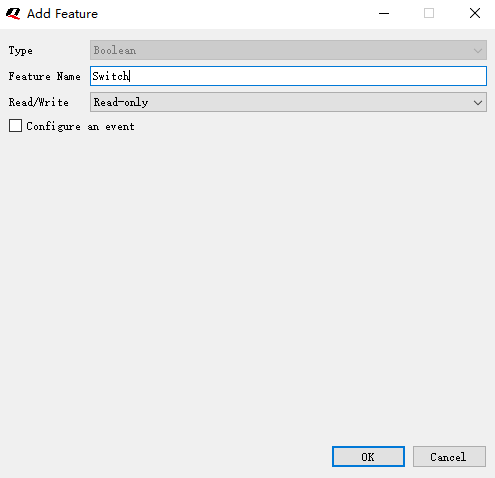
- Type: Set this parameter to "Boolean". For example, "True" indicates the hygrothermograph is switched on.
- Feature Name: Name of the slave feature, such as "Switch".
- Read/Write: It can be set to "Read-only", "Write-only" or "Read & Write".
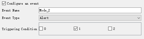
Configure an event (Optional)
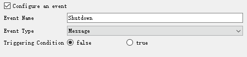
- Event Name: Name of the event.
- Event Type: "Message", "Alert" and "Fault".
- Triggering Condition: Condition that triggers the event. When the Modbus slave data queried by the DTU device matches the set value, the event is triggered.
2) Add a Numeric Feature
Add the features of temperature and humidity to view the temperature and humidity of the sensor on Developer Center.

- Type: Set this parameter to "Number". For example, “25.63” indicates the temperature of the sensor.
- Feature Name: Name of the slave feature, such as "Temperature".
- Read/Write: It can be set to "Read-only", "Write-only" or "Read & Write".
- Data Type: The range of values that can be stored in a variable of this type. For example, to account for negative Celsius degrees and a range from -40 to 85, it is more appropriate to set it to "16-bit Signed Int".
- Byte Order: The order in which data is stored in memory. For example, for a 32-bit integer, a number (ABCD) is stored in two bytes, where the high-order byte is (AB) and the low-order byte is (CD), choose from:
- Big Endian: The high-order byte comes first, and the low-order byte comes last, i.e., it is stored as (ABCD).
- Little Endian: The low-order byte comes first, and the high-order byte comes last, i.e., it is stored as (DCBA).
- Big Endian Byte Swapped: Big-endian mode with high and low bytes swapped in pairs, i.e., it is stored as (BADC).
- Little Endian Byte Swapped: Little-endian mode with high and low bytes swapped in pairs, i.e., it is stored as (CDAB).
- Reduction Formula: Convert a value to another format. For example, if the sensor reads the value 0x0A 0x03 (2563 in decimal) and the reduction formula is 2563 *0.01+0=25.63, then 25.63 is the actual temperature.
Configure an event (Optional)
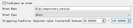
- Event Name: Name of the event.
- Event Type: "Message", "Alert" and "Fault".
- Triggering Condition: Condition that triggers an event. The value entered in the later box must be greater than the one in the prior box. When the Modbus slave data queried by the DTU device falls within the set range, the event will be triggered.
3) Add a Feature in Byte Stream
Add the time stamp feature to read or set the time stamp of the sensor on Developer Center.
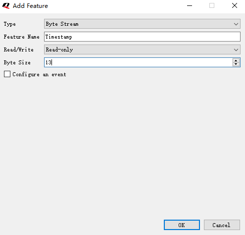
- Type: Set this parameter to "Byte Stream", such as "ABCabc123#&*".
- Feature Name: Name of the slave feature, such as "timestamp".
- Read/Write: It can be set to "Read-only", "Write-only" or "Read & Write".
- Byte Size: Set this parameter according to the maximum byte length of byte stream data.
Configure an event (Optional)
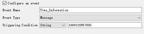
- Event Name: Name of the event.
- Event Type: "Message", "Alert" and "Fault".
- Triggering Condition: Condition that triggers an event. If the byte stream or string you entered in the box is read on Developer Center, the event will be triggered.
4) Add a Feature in Enumeration
Add the mode setting feature to get or set the current mode of the sensor on Developer Center.

- Type: Set this parameter to "Enumeration".
- Feature Name: Name of the slave feature, such as "Working Mode".
- Read/Write: It can be set to "Read-only", "Write-only" or "Read & Write".
- Data Type: Select a data type consistent with the register data type.
- Byte Order: The order in which data is stored in memory. For example, for a 32-bit integer, a number (ABCD) is stored in two bytes, where the high-order byte is (AB) and the low-order byte is (CD), choose from:
- Big Endian: The high-order byte comes first, and the low-order byte comes last, i.e., it is stored as (ABCD).
- Little Endian: The low-order byte comes first, and the high-order byte comes last, i.e., it is stored as (DCBA).
- Big Endian Byte Swapped: Big-endian mode with high and low bytes swapped in pairs, i.e., it is stored as (BADC).
- Little Endian Byte Swapped: Little-endian mode with high and low bytes swapped in pairs, i.e., it is stored as (CDAB).
Configure an event (Optional)
- Event Name: Name of the event.
- Event Type: "Message", "Alert" and "Fault".
- Triggering Condition: Condition that triggers an event. If any property value you set is read on Developer Center, the event will be triggered.。
6. Generate Configuration File
Click "Configuration File" >"Generate" in the tool bar, then select the file path in the pop-up window.

If the configuration file is successfully generated, the files in the following two formats will be generated in the selected file path.
- xxxxxx_xxxxxxxxxx_xxxxx.json: TSL model definition file, which is used to import the configuration to Developer Center.
- xxxxxx_xxxxxxxxxx_local.bin: Modbus definition file, which is used to download the configuration to the device.
7. Import Configuration File to Developer Center
Log in to Developer Center, select the corresponding product on the "Product Management" page, enter the "Define Feature" tab and click "Draft Mode" to edit.
Click "Import" - "Import TSL Model" - "Upload“.
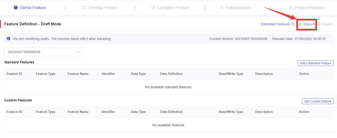
- Select the generated xxxxxx_xxxxxxxxxx_xxxxx.json file in the pop-up window, and click "Confirm" to import the configuration file.

- Click "Save Changes", check the box in the pop-up window and click "Submit" to exit draft mode.

Operations on Device
1. Program Code
1) Initialize QuecThing
QuecOpen SDK provides APIs for reading and writing device information and corresponding reference implementation, which can be customized as needed. The device carries the information to establish a connection with Developer Center.
c
oprt_ret ret = OPRT_OK;
Qth_eventCb_t event_cb = {0};
Qth_otaEventCb_t otaCb = {0};

ret = Qth_devInit();
if (OPRT_OK != ret)
{
    Quos_logPrintf(APPS_OPEN, LL_ERR, "sdk init error:%d", ret);
    return;
}
otaCb.planExCb = otaPlanExCb;
otaCb.sotaInfoCb = sotaInfoCb;
otaCb.sotaFileCb = sotaFileCb;
event_cb.devEventCb = devEventCb;
event_cb.ttlvRecvCb = ttlvRecvCb;
event_cb.otaEventCb = otaCb;
Qth_configSetEventCb(event_cb);
2) Initialize Modbus Components
To initialize ModBus components, you must register the serial port list used for downloading the configuration file, as well as the functions of modbusUartSend() and modbusInitCb().
c
/* Initialize Modbus. */
Ql_iotMBInit(portList,sizeof(portList)/sizeof(quint16_t),modbusUartSend,modbusInitCb);
i. After the ModBus component is initialized, the device information from the configuration file is passed into the callback function. Send and receive data through the serial port and connect the device to Developer Center within the function.
c
qbool modbusUartSend(quint16_t port, const quint8_t *buf, quint32_t bufLen)
{
    oprt_ret ret = Qhal_uart_write(port, (void *)buf, bufLen);
    if(ret >= 0)
    {
        return TRUE;
    }
    else
    {
        return FALSE;
    }
}
ii. This callback function is called when the ModBus component needs to send data to the serial port. Implement the serial port data-sending capability within this function.
c
void modbusInitCb(char *pk, char *ps, QIot_MBPortCfg_t *portInfo[], quint32_t portNum)
{
    if (NULL == pk || NULL == ps || NULL == portInfo || 0 == portNum)
    {
        Quos_logPrintf(APPS_OPEN, LL_DBG, "MODBUS init fail");
        return;
    }
    /* Configure PK/PS and connect the device to Developer Center. */
    Qth_configSetProductInfo(pk, ps);
    Qth_devStart();
}
3) Process Downlink Data
After receiving the command from Developer Center, the device converts TTLV data into Modbus data and sends it through the registered sending interface.
c
void ttlvRecvCb(void *ttlvHead)
{
    Quos_logPrintf(APPS_OPEN, LL_DBG, "recv ttlv write");
    Ql_iotMBCloudRecv(ttlvHead);
}
2. Compile and Download Program
Note: As the download program of each DTU-Modbus module may vary, please contact Acceleronix Technical Support support@acceleronix.io for details."
3. Download Configuration File to DTU Device
Click "Download" > "Download Through Serial Port" in the toolbar.
Click "Import", and select the generated xxxxxx_xxxxxxxxxx_local.bin file in the pop-up window.
After selecting the baud rate, port number, or other configurations, click "Open Serial Port". Note: You can find the corresponding download serial port according to the PIN on the EVB or the schematic diagram.
Click "Download" and restart the hardware device. The download progress will be displayed in the text box. A "Downloaded Successfully" window will pop up after a successful download.
Presentation
1. Device Online
Once the firmware is downloaded into the DTU device, the device will automatically connect to Developer Center. Subsequently, the device will be added to the corresponding product and authenticated automatically.
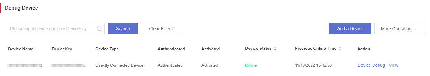
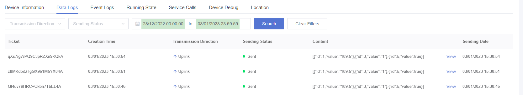
2. Check Data Logs
You can view the DTU device's regular data acquisition from the slave every 60 seconds and transmission to Developer Center on the "Device Details" > "Data Logs" page.
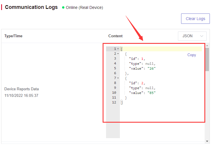
The uploaded temperature value of 25.68 and humidity value of 65.13 can be viewed on the "Device Debug" > "Communication Logs" defined by the TSL model.
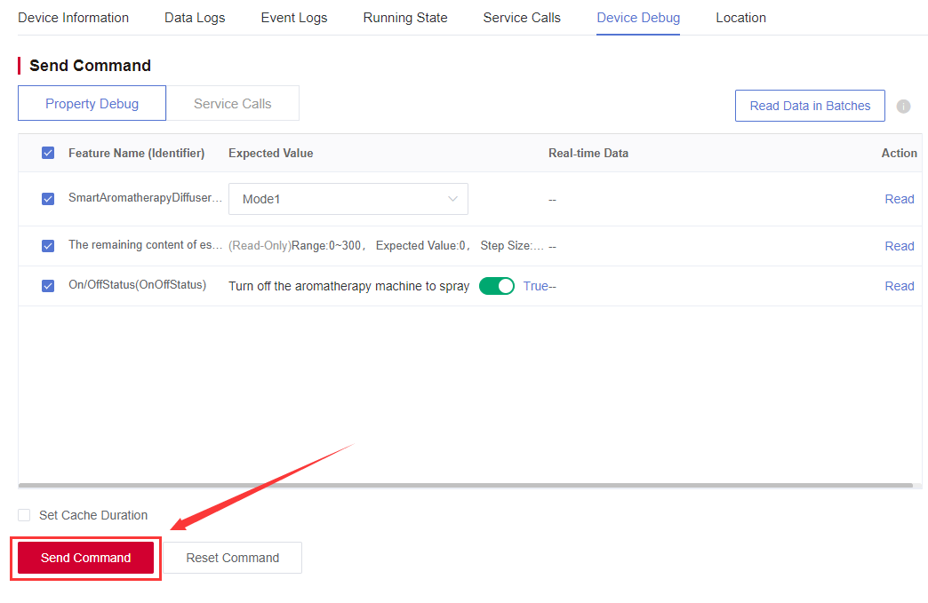
3. Send Command
Developer Center sends commands to the DTU-Modbus device, and the DTU device calls the callback function to process the command, converts the data into the Modbus data through the serial port and sends the data to the hygrothermograph sensor. The hygrothermograph sensor then receives the time stamp and switch command issued by the Developer Center through the DTU device.