
Appearance
User Manual
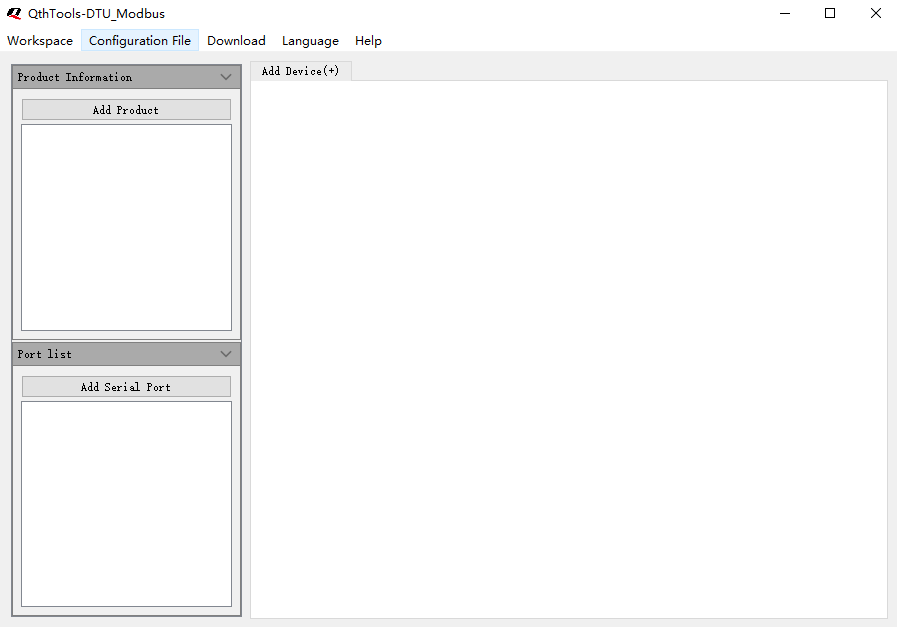
Homepage Introduction
Workspace: Import, export, and clear the current workspace configuration info.
Configuration File :Generate Developer Center TSL model files and files for device burning.
Download :Download the file to the device through the serial port.
Help :View documentation, contact information, software version number.
Product Information: Product information defined in Developer Center, such as ProductKey, ProductSecret.
Port list : Serial port information of the DTU device, such as serial port ID, baud rate, etc. Slave device info: Information about the slave device, such as slave device name, address, etc.
Configure Product Information
Product Name: User-defined name for the product. It is recommended to use a name consistent with that on Developer Center.
ProductKey : The globally unique identifier issued by Developer Center for the product. ProductKey is very important and will be used in device authentication and communication. Please keep it safe.
ProductSecret : It is issued by Developer Center for each product in combination with a ProductKey. It is essential to keep ProductSecrets safe, as they are required for unique-PS-per-PK authentication.
Report Method
Report All : The data polled by the device will be directly reported to Developer Center.
Report Changes: The data polled by the device each time is compared with the last data, and only changes are reported to Developer Center. Device type
Directly Connected Device: A Modbus slave device and the gateway share product info,and they are displayed on Developer Center as one device.
Gateway Sub-device : Modbus slave devices have independent product info and device info, and are displayed separately on Developer Center.
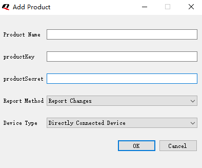
Add Product Info
- Click the "Add product" button
- In the pop-up window, enter the following parameters: "Product name", "ProductKey", "ProductSecret", "Report method", and "Device Type".
- Click "OK".
Note: You can only add one piece of product information at a time. If you need to add other information, you must first modify or delete the existing one.
Modify Product Info
- Right-click on the product info that needs to be modified.
- Click the "Edit" button on the right-click menu.
- In the pop-up window, modify the following parameters: "Product name", "ProductKey", "ProductSecret", "Report method", and "Device type".
- Click "OK".
Delete Product Info
- Right-click on the product info that needs to be deleted.
- Click the "Delete" button in the right-click menu.
Configure Port Info
Port number: Port number used by the module. Range: 0–99.
Polling interval : Time interval between consecutive Modbus polls of all register data. Unit: second.
Command interval : Time interval between sending Modbus commands. Unit: millisecond.
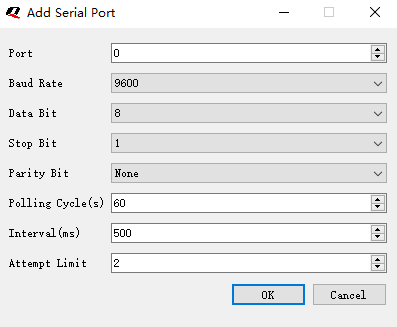
Add Port Info
- Click the "Add port" button.
- In the pop-up window, enter the following parameters: "Port"(Port number), "Baud Rate", "Data Bit", "Stop Bit", "Check bit", "Polling Cycle(s)", "Interval(ms)", and "Attempt Limit".
- Click "OK".
Modify Port Info
- Right-click on the port info that needs to be modified.
- Click the "Edit" button on the right-click menu.
- In the pop-up window, modify the following parameters: "Port", "Baud rate", "Data bit", "Stop bit", "Check bit", "Polling Cycle(s)", "Interval(ms)", and "Attempt Limit".
- Click "OK".
**Delete Port Info **
- Right-click on the port info that needs to be deleted.
- Click the "Delete" button in the right-click menu.
Configure Slave Device
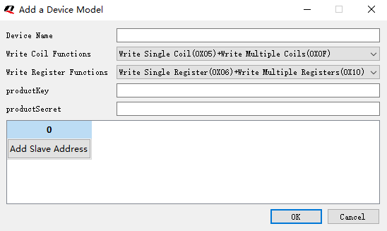
Add Slave Device
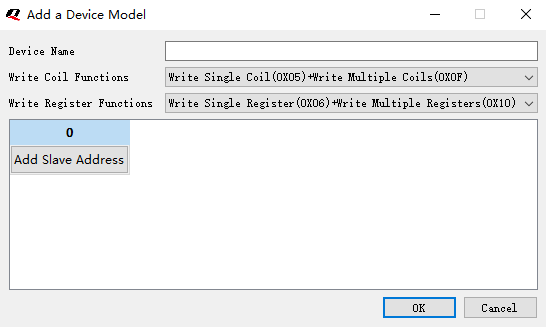
- Click the “Add device(+)” button.
- In the pop-up window, enter a "Device name". For example, if the device is a temperature and humidity sensor probe, you can enter "temperature and humidity sensor" here.
- Enter the Modbus slave address of the device in the list corresponding to the port number. For example, the temperature and humidity sensor probe is connected to serial port 0 and its Modbus address is 1, enter 1. If there are multiple devices that need to set to different Modbus slave addresses, add multiple devices in a batch.
- If the device is selected as a "Gateway sub-device", you need to fill in the corresponding product information for the Modbus slave device: ProductKey, ProductSecret.
- Click "OK".
Modify Slave Device
- Right-click on the device info that needs to be modified.
- Click the "Edit" button on the right-click menu.
- In the pop-up window, modify the following parameters: "Device name", and "Slave address".
- Click "OK".
Delete Slave Device
- Right-click on the device info that needs to be modified.
- Click the "Delete" button on the right-click menu.
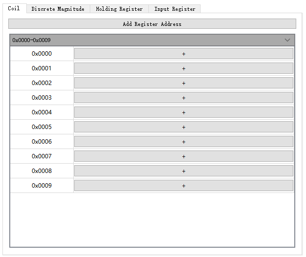
Configure Register List
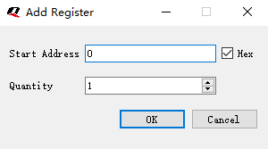
Add Register List
- Select the tab page for Coil, Discrete Inputs, Holding register, Input Register.
- Click the “Add Register Address” button.
- In the pop-up window, modify the following parameters: "Start Address", and "Quantity".
- Click the "Hex" button to switch whether the input box of "Start Address" is displayed in decimal or hexadecimal.
- Click "OK".
Modify Register List
- Right-click the header of the register list that needs to be modified.
- Click the "Edit" button on the right-click menu.
- In the pop-up window, modify the following parameters: "Start Address", and "Quantity".
- Click "OK".
Delete Register (Coil) List
Delete Whole Register (Coil) List
- Right-click the header of the register (coil) list that needs to be deleted.
- Click the "Delete" button on the right-click menu.
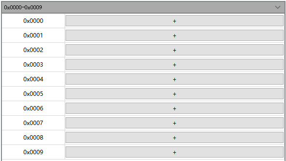
Delete Part of Register (Coil) List
- Right-click the register address that needs to be deleted.
- Click the "Delete to Top" or "Delete to Bottom" button in the right-click menu.
- Click "Yes" in the prompt box.
Configure Feature Label of Register (Coil)
Configure Feature Info
Type : Feature type defined according to the type of data provided by the Modbus slave device.
- Boolean type :This feature type is used for switches, relays, or any devices with only two possible statuses: 0 and 1.
- Numeric type :This feature type is used for integer or floating point number data. It is widely used in Modbus.
- Byte stream : This feature type is used for transmitting data in the form of a byte stream or string type.
- Enumeration : This feature type is used when there are a limited number of possible values for a feature and you need to list all possible values and give each of them a name.
Add Feature Info
Add Boolean Feature
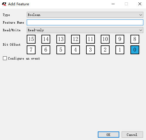
- Type: Set this parameter to "Boolean".
- Feature Name: Name of the slave feature.
- Read/Write: It can be set to "Read-only", "Write-only" or "Read & Write".
Configure an event (Optional)
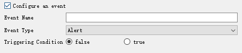
- Event Name: Name of the event.
- Event Type: "Message", "Alert" and "Fault".
- Triggering Condition: Condition that triggers the event. It is based on the value of a specific register and defined by setting a range of values. When the value of the register falls within that range, the event will be triggered.
Add Numeric Feature
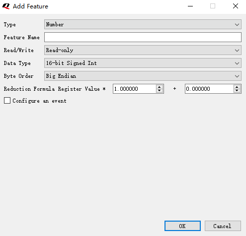
- Type: Set this parameter to "Number".
- Feature Name: Name of the slave feature.
- Read/Write: It can be set to "Read-only", "Write-only" or "Read & Write".
- Data Type: It should be selected according to Modbus protocol actual data type.
- Byte Order: It should be selected according to the actual byte order used by the device.
Byte order
16-bit signed int/16-bit unsigned int:
- Big endian (AB)
- Little endian (BA)
- Big endian byte swapped (BA-swapped)
- Little endian byte swapped (AB-swapped)
32-bit signed int/32-bit unsigned int:
- Big endian (ABCD)
- Little endian (DCBA)
- Big endian byte swapped (BADC-swapped)
- Little endian byte swapped(CDAB-swapped)
64-bit signed int/64-bit unsigned int:
- Big endian (ABCDEFGH)
- Little endian (HGFEDCBA)
- Big endian byte swapped (BADCFEHG-swapped)
- Little endian byte swapped (GHEFCDAB-swapped)
32-bit single-precision floating-point:
- Big endian (ABCD)
- Little endian (DCBA)
- Big endian byte swapped (BADC-swapped)
- Little endian byte swapped (CDAB-swapped)
64-bit double-precision floating-point:
- Big endian (ABCDEFGH)
- Little endian (HGFEDCBA)
- Big endian byte swapped (BADCFEHG-swapped)
- Little endian byte swapped (GHEFCDAB-swapped)
Conversion formula
Data report :cloudValue = localValue*multiple+increment
Data sent :localValue = (cloudValue-increment)/multiple
- cloudValue: Data issued by Developer Center
- localValue: Data of the Modbus slave device read by the device
- Multiple: Attenuation multiple is the value multiplied by the register value in the conversion formula interface
- Increment : Increment is the value added to the register value in the conversion formula interface
For example:
In a slave device, the value read by the register is 350. According to the device user manual, the actual temperature is 350 x 0.1 = 35 ℃, so Multiple should be filled with 0.1, and Increment should be filled with 0.
localValue=10,multiple=0.1,increment=0.01,cloudValue=10*0.01+0.01=0.11
cloudValue=0.11,multiple=0.01,increment=0.01,localValue=(0.11-0.01)/0.01=10
Data Conversion Path
- Data report: Byte swapped -> Numeric conversion
- Data sent: Numeric conversion -> Byte swapped
Configure an event (Optional)
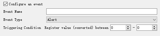
- Event Name: Name of the event.
- Event Type: "Message", "Alert" and "Fault".
- Triggering Condition: Condition that triggers the event. The value entered in the second box must be greater than the one in the first box. When the corresponding value of the register is queried, and its value falls within the set range, the event will be triggered.
Add Byte Stream Feature
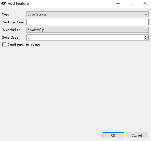
- Type: Set this parameter to "Byte Stream".
- Feature Name: Name of the slave feature.
- Read/Write: It can be set to "Read-only", "Write-only" or "Read & Write".
- Byte Size: Set this parameter to the maximum byte length of byte stream data that will be transmitted.
Configure an event (Optional)
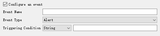
- Event Name: Name of the event.
- Event Type: "Message", "Alert" and "Fault".
- Triggering Condition: Condition that triggers the event. If the byte stream or string you entered in the box is read on Developer Center, the event will be triggered.
Add Enumeration Feature

- Type: Set this parameter to "Enumeration".
- Feature Name: Name of the slave feature.
- Read/Write: It can be set to "Read-only", "Write-only" or "Read & Write".
- Data Type: Select a data type consistent with the register data type.
- Byte Order: The order of data stored in memory. For instance, in case of a 32-bit integer, a number (ABCD) is stored in two bytes, where the high-order byte is (AB) and the low-order byte is (CD).
- Big Endian: The high-order byte comes first, and the low-order byte comes last, i.e., it is stored as (ABCD).
- Little Endian: The low-order byte comes first, and the high-order byte comes last, i.e., it is stored as (DCBA).
- Big Endian Byte Swapped: The data is stored in big-endian format, but there's a swap between high and low bytes in pairs, that is, it is stored in the form of (BADC).
- Little Endian Byte Swapped: The data is stored in little-endian format, but there's a swap between high and low bytes in pairs, that is, it is stored in the form of (CDAB).
Configure an event (Optional)

- Event Name: Name of the event.
- Event Type: "Message", "Alert" and "Fault".
- Triggering Condition: Condition that triggers the event. If any property value you have set is read on Developer Center, the event will be triggered (Multiple-choice).
Modify Feature Label of Register
- Right-click the feature label that needs to be modified.
- Click the "Edit" button in the right-click menu.
- In the pop-up window, modify the following parameters: "Feature name", and "Read&Write type".
- Click "OK".
Delete Feature Label of Register
- Right-click the feature label that needs to be deleted.
- Click the "Delete" button in the right-click menu.
Workspace Info
Import Workspace Info
- Click "Workspace" -> "Open" button in the menu bar.
- In the pop-up window, select the workspace file you want to open.
- Click "Open" to confirm.
Export Workspace Info
- Click "Workspace" -> "Save" button in the menu bar.
- In the pop-up window, select the path where you want to save the file.
- Click "Save" to confirm.
Clear Workspace Info
- Click "Workspace" -> "Clear" button in the menu bar.
Note: This operation will delete all workspace information permanently and cannot be undone. Please proceed with caution.
Configuration File
Generate Configuration File
- Click "Configuration File" -> "Generate" button in the menu bar.
- Select the file path in the pop-up window.
- Click "Save" to confirm.
Note: xxxxxx_xxxxxxxxxx_cloud.json: TSL file that is imported to Developer Center
xxxxxx_xxxxxxxxxx_local.bin: Modbus file that is downloaded to the device
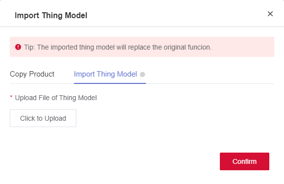
Import Configuration File to Developer Center
- Log in to Developer Center, open the product page, and switch to "Function Definition" page.
- Click "Draft Mode" to enter editing mode.
- Click "Import"-> "Import TSL".
- Select the generated xxxxxx_xxxxxxxxxx_cloud.json file in the pop-up window.
- Click "Confirm" to import.
- Click "Release" to exit editing mode.
Download Configuration File to Device
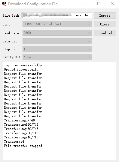
- Click "Download" -> "Download Through Serial Port" button in the menu bar.
- Click "Import"
- Select the generated xxxxxx_xxxxxxxxxx_local.bin file in the pop-up window.
- Select the corresponding port number.
- Click "Open Serial Port"
- Click "Download"
- Reboot the device.
- The file download progress will be displayed in a textbox. If the download is completed successfully, a prompt "Download Succeeded" will pop up.
Appendix Term and Abbreviation
Table 1: Terms and Abbreviations
| Abbreviation | Description |
|---|---|
| USB | Universal Serial Bus |